Hello - my apologies if I ask for something stupid but I am new to this forum and would love to take the advice of you guys:D
Would anyone be able to show me a wiring diagram for the grounding of this board. In one of Silent art's early posts he explains there are four points but the post is a bit unclear to me. Looks like there was once a picture but it is missing from the post?
In addition, - and once again this may be the most obvious question ever the 5v/0 molex connector near the relays, is this just for a simple dpdt switch connected to the molex connector to turn on the true bypass (and an LED) on?
Thanks in advance. This forum is an amazing source of talent.
Deuce
Dual La2a - [silent:arts] version
-
[silent:arts]
- Beiträge: 3520
- Registriert: Sa Jun 10, 2006 5:54 pm
- Wohnort: BLN
- Kontaktdaten:
Awesome Volker thanks. That diagram makes sense to me.
In addition, can I clarify the following:
1) The bypass switch(s) - is this just a straight connection from a spdt switch to the Relay 5v/0 molex connector on each side of the audio?
2) NE2 - the only ones I can find in Australia are either 70v or 90v. Will a 70v substitute for the 65v one?
3) What does the 5v/0 o the DC circuit molex connect to?
4) Is there a a schematic available for this circuit? I have a feeling these questions may be very obvious if I had a schematic to read.
Thanks
-
[silent:arts]
- Beiträge: 3520
- Registriert: Sa Jun 10, 2006 5:54 pm
- Wohnort: BLN
- Kontaktdaten:
you apply 5V from the 5V PSU to the 5V relays. 5V is compressor in, 0V is compressor outDeuce43 hat geschrieben:1) The bypass switch(s) - is this just a straight connection from a spdt switch to the Relay 5v/0 molex connector on each side of the audio?
don't know, but you can use a zener diode instead of the neonDeuce43 hat geschrieben:2) NE2 - the only ones I can find in Australia are either 70v or 90v. Will a 70v substitute for the 65v one?
see 1)Deuce43 hat geschrieben:3) What does the 5v/0 o the DC circuit molex connect to?
yes. schematicDeuce43 hat geschrieben:4) Is there a a schematic available for this circuit?
volker
olafmatt hat geschrieben:Strom kann tot machen
-
[silent:arts]
- Beiträge: 3520
- Registriert: Sa Jun 10, 2006 5:54 pm
- Wohnort: BLN
- Kontaktdaten:
since I don't plan any further runs of this PCB I forwarded the production files to Gustav.
may be your last chance if you want to get some PCBs for this project:
http://www.prodigy-pro.com/diy/index.php?topic=31633.0
may be your last chance if you want to get some PCBs for this project:
http://www.prodigy-pro.com/diy/index.php?topic=31633.0
volker
olafmatt hat geschrieben:Strom kann tot machen
Dear Voker and others
On page three of this thread I think there was a diagram for wiring the heaters near the 100r resistors and ground. Any chance this could be added again so I can see it?.
In addition, once again I am a bit confused with the 5vdc circuit:
1) There appears to be 2 different 5dc points on the board. The first says "relais" and I am guessing this is for the bypass switch and relay points . But also at the top of the board there are both 5v and ground holes near the power supply ground connection. I guess the 5dc ground can be connected to the power supply ground and others audio grounds, but what is the 5vdc point next to this for?
2) I also want to power some LED's in this project. How much current does the 5vdc circuit put out? Is it enough current to connect both the relays and also some leds wired in parallel from the 5dc relay points?
Thanks and sorry for such lame questions.
Ok I think I have found the answer to the 5vdc and its my own stupidity.
The other 5vdc ( ie not the relais point) is just the ground point for the dc reference circuit only! So without annnoying anyone with such a stupid qustion, the only 5v supply on the DC reference circuit is the one marked Relais?
Thanks once again
The other 5vdc ( ie not the relais point) is just the ground point for the dc reference circuit only! So without annnoying anyone with such a stupid qustion, the only 5v supply on the DC reference circuit is the one marked Relais?
Thanks once again
-
[silent:arts]
- Beiträge: 3520
- Registriert: Sa Jun 10, 2006 5:54 pm
- Wohnort: BLN
- Kontaktdaten:
Hi folks
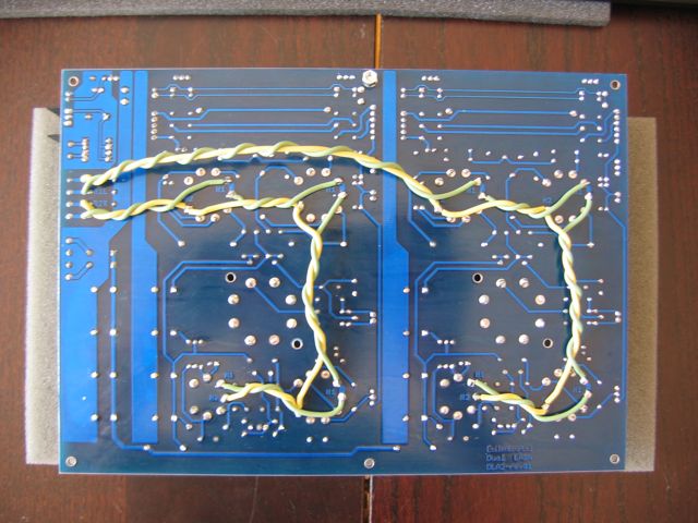
Can anyone show a picture of the heater wiring on the underside of the PCB?
In addition, the pads for the limit/compress switch appear to be connected on my board when I test them. I have looked at the board closely and I cant find any solder bridge between the two contact pads. Is this normal or have I dont something wrong?
Thanks very much
Hi,
the heater wiring is quite easy: strip wires from R1 and R2 to H1 and H2 for the left channel and from R3 and R4 to H1 and H2 for the right channel. The wires for each channel should be twisted. The pads for limit/compress on the pcb should´nt be connected. It´s the switch that connects them.
regards
Bernd
-
[silent:arts]
- Beiträge: 3520
- Registriert: Sa Jun 10, 2006 5:54 pm
- Wohnort: BLN
- Kontaktdaten: